Measure the off resistance across the FET (source-drain) in the IRF7413s? At least to compare against the new ones you've already ordered before soldering replacements in?
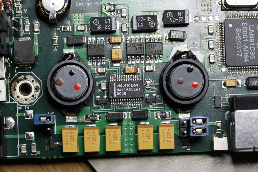
From what you're saying I'd probably be blaming the MAX1631 actually. i.e. it's gone a bit mental and turned on both FETs resulting in essentially a dead short on the input supply.
Yeah, that does seem a bit more probable than two separate chips suddenly both going bad at the same time -- except I suppose if one of them did go bad, the MAX1631 would likely crank up the other one and try to fry both..
Mmm... okay, I just measured the two that were removed: one shows about 10.5 Ohms, whereas the other shows infinity (my meter only goes up to 2MO). Since they should be identical, this means that at least one of the two has gone bad.
That said the heat from the "induced" short may have since killed the IRF7413 chips.
Yeah, they do get rather hot. There's a 2.5A fuse on the 12V supply, and the IRF7413s are rated for 3.1A, though where all that wattage is supposed to go is beyond me!
I don't know if there's anyway you could diagnose the MAX1631 whilst installed with no FETs. I would expect the "top" FET would be turned hard (since the controller will not be seeing any output). At least I'd expect the "bottom" FET to be off in that situation.
Yeah, I can check that. It is outputing the "permanent +5V" line properly now, though, so portions are still okay. But the 0V on the 3.3V outs has me a bit stumped -- perhaps I have to trigger the MAX1631 to "on" or something to see that ?
Thanks


 Previous Topic
 Index
Index